Computer-Aided Design (CAD) Applied to Process and Instrumentation Diagrams
Realize your P&ID quickly
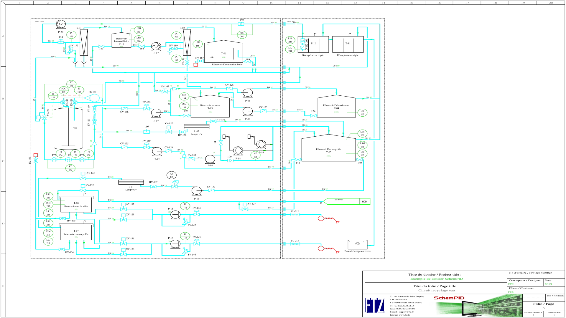
With proven ergonomics, SchemPID allows you to create your process and instrumentation plans in an intuitive and simple way.
Spread of information
Dedicated propagation functions are present in the software and avoid re-entry and errors. A multi-page management makes it possible to link the P&IDs between them.
Numbers are managed automatically
SchemPID predefined and automates the numbering of plan elements, symbols and lines. Mark formats are customizable.
Data centralization
The software embeds list generation tools that allow you to have consistency between the extracted files (csv, excel) with the diagram produced
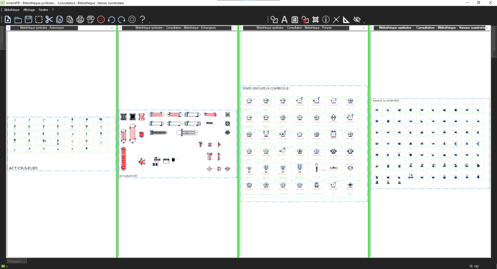
Adapted libraries
SchemPID provides a complete set of standardized symbol libraries (IEC, ISO, ISA, ANSI, …), guaranteeing a quick start.
The software in detail
Schematic
Instruments and Loops
BOMs
Libraries
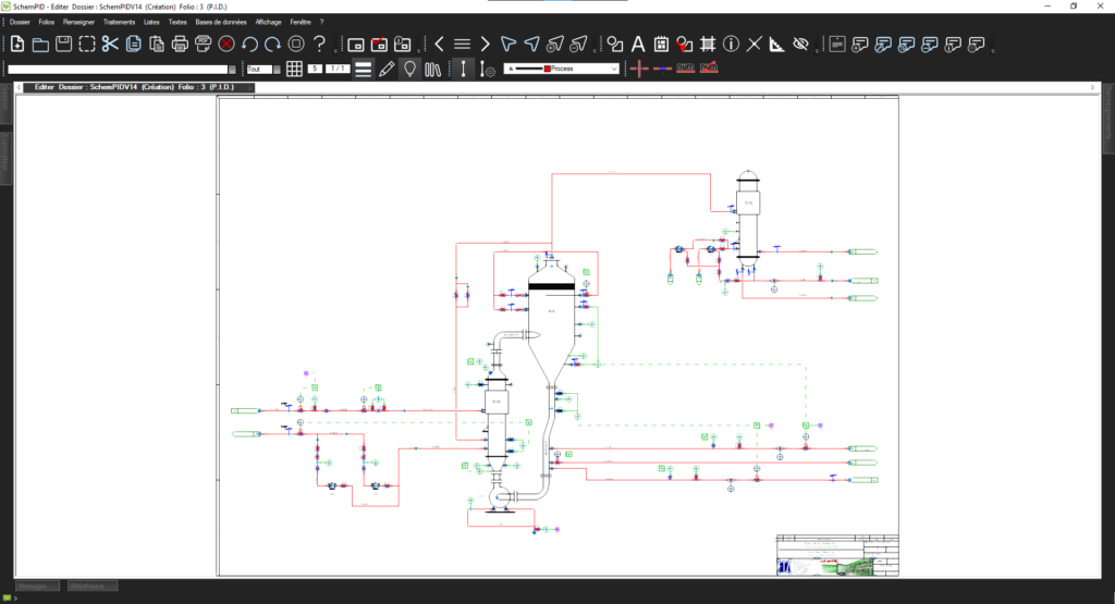
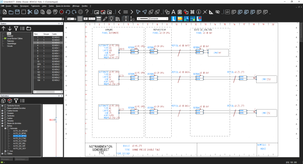
With SchemPID, you benefit from a user-friendly and intuitive interface that allows you to easily create your schematic folios with simple and quick commands accessible through context menus.
The placement of equipment, accessories, instruments, PLC input/output, piping elements, and other components is simplified and automated. You can easily place and connect these symbols on your diagrams with just a few clicks, speeding up the design process.
With SchemPID, creating your diagrams becomes a smooth and efficient process, allowing you to design high-quality schematic folios while saving time with its advanced features.
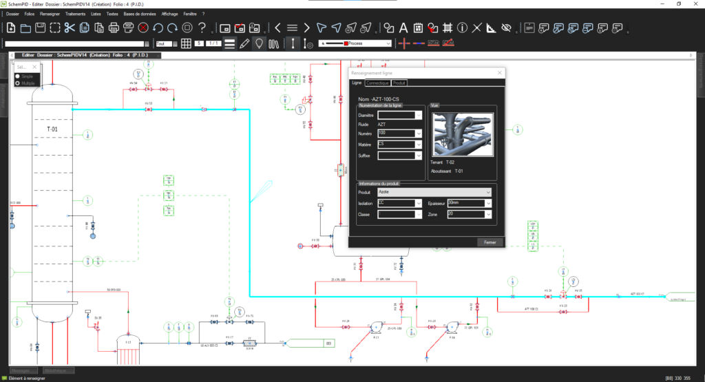
SchemPID offers an advanced numbering feature for piping lines and equipment in P&ID schematics. This function allows automatic numbering based on specific attributes and an order number.
The software provides great flexibility in numbering formats, allowing you to customize the schematics according to your needs. Dynamic checking is performed to avoid duplicates and ensure the uniqueness of references.
With SchemPID, numbering piping lines and equipment becomes simple, accurate, and efficient, allowing you to organize your P&ID schematics with precision and reliability.
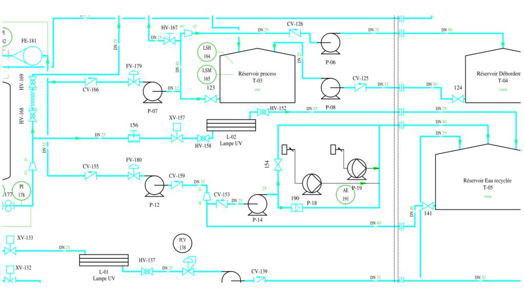
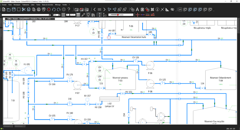
In SchemPID, the placement of components is automatically controlled based on the flow direction of the fluid, ensuring a logical and coherent layout. Additionally, flexible parameter settings allow for the management of line-cutting priorities while preserving the uniqueness of each line in the diagram.
Another important aspect of SchemPID is its automatic or manual control of fluid and pipe diameter information dissemination. This control ensures that essential information such as fluid properties and pipe diameters are accurately transmitted and displayed in the diagram.
With SchemPID, you have a powerful tool that facilitates component placement, line-cutting management, and the dissemination of relevant information. Whether you are working on simple or complex piping projects, SchemPID supports you in creating clear, accurate, and industry-standard compliant diagrams.
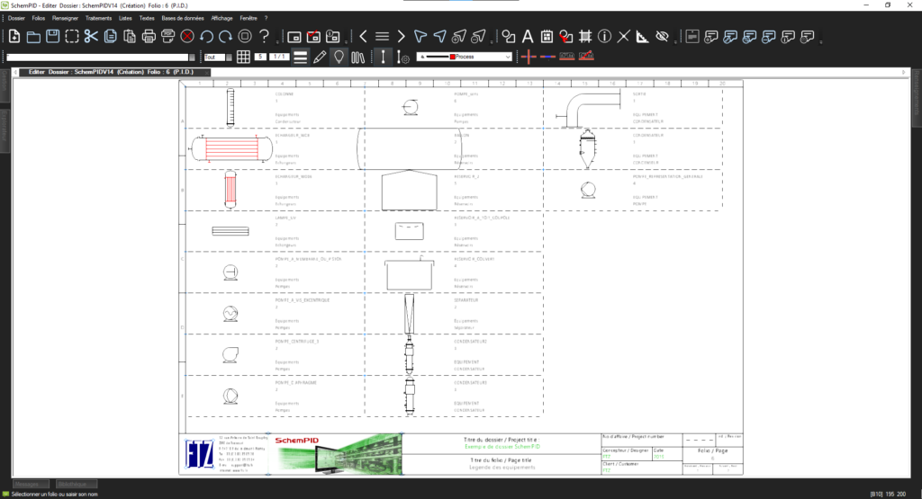
SchemPID offers a powerful feature for the automatic generation of legends, thereby enhancing the overall understanding of the schematics. Legends are generated using the symbols placed in the project, ensuring an accurate correspondence between the symbols and their meanings.
This feature adds an additional layer of information to the schematics, making them easier to read and interpret. The legends created by SchemPID provide clear and precise information about the symbols used, their function, and their role in the diagram.
With SchemPID, you can create customized legends that cater to the specific needs of your project. This functionality contributes to a better understanding of the diagram and facilitates more effective communication among project stakeholders.
The automatic creation of legends by SchemPID is a convenient and efficient way to enhance the readability and clarity of schematics, thereby facilitating the work of industry professionals.
With SchemPID, you benefit from a user-friendly and intuitive interface that allows you to easily create your schematic folios with simple and quick commands accessible through context menus.
The placement of equipment, accessories, instruments, PLC input/output, piping elements, and other components is simplified and automated. You can easily place and connect these symbols on your diagrams with just a few clicks, speeding up the design process.
With SchemPID, creating your diagrams becomes a smooth and efficient process, allowing you to design high-quality schematic folios while saving time with its advanced features.
SchemPID offers an advanced numbering feature for piping lines and equipment in P&ID schematics. This function allows automatic numbering based on specific attributes and an order number.
The software provides great flexibility in numbering formats, allowing you to customize the schematics according to your needs. Dynamic checking is performed to avoid duplicates and ensure the uniqueness of references.
With SchemPID, numbering piping lines and equipment becomes simple, accurate, and efficient, allowing you to organize your P&ID schematics with precision and reliability.
In SchemPID, the placement of components is automatically controlled based on the flow direction of the fluid, ensuring a logical and coherent layout. Additionally, flexible parameter settings allow for the management of line-cutting priorities while preserving the uniqueness of each line in the diagram.
Another important aspect of SchemPID is its automatic or manual control of fluid and pipe diameter information dissemination. This control ensures that essential information such as fluid properties and pipe diameters are accurately transmitted and displayed in the diagram.
With SchemPID, you have a powerful tool that facilitates component placement, line-cutting management, and the dissemination of relevant information. Whether you are working on simple or complex piping projects, SchemPID supports you in creating clear, accurate, and industry-standard compliant diagrams.
SchemPID offers a powerful feature for the automatic generation of legends, thereby enhancing the overall understanding of the schematics. Legends are generated using the symbols placed in the project, ensuring an accurate correspondence between the symbols and their meanings.
This feature adds an additional layer of information to the schematics, making them easier to read and interpret. The legends created by SchemPID provide clear and precise information about the symbols used, their function, and their role in the diagram.
With SchemPID, you can create customized legends that cater to the specific needs of your project. This functionality contributes to a better understanding of the diagram and facilitates more effective communication among project stakeholders.
The automatic creation of legends by SchemPID is a convenient and efficient way to enhance the readability and clarity of schematics, thereby facilitating the work of industry professionals.
With SchemPID, you benefit from a user-friendly and intuitive interface that allows you to easily create your schematic folios with simple and quick commands accessible through context menus.
The placement of equipment, accessories, instruments, PLC input/output, piping elements, and other components is simplified and automated. You can easily place and connect these symbols on your diagrams with just a few clicks, speeding up the design process.
With SchemPID, creating your diagrams becomes a smooth and efficient process, allowing you to design high-quality schematic folios while saving time with its advanced features.
SchemPID offers an advanced numbering feature for piping lines and equipment in P&ID schematics. This function allows automatic numbering based on specific attributes and an order number.
The software provides great flexibility in numbering formats, allowing you to customize the schematics according to your needs. Dynamic checking is performed to avoid duplicates and ensure the uniqueness of references.
With SchemPID, numbering piping lines and equipment becomes simple, accurate, and efficient, allowing you to organize your P&ID schematics with precision and reliability.
In SchemPID, the placement of components is automatically controlled based on the flow direction of the fluid, ensuring a logical and coherent layout. Additionally, flexible parameter settings allow for the management of line-cutting priorities while preserving the uniqueness of each line in the diagram.
Another important aspect of SchemPID is its automatic or manual control of fluid and pipe diameter information dissemination. This control ensures that essential information such as fluid properties and pipe diameters are accurately transmitted and displayed in the diagram.
With SchemPID, you have a powerful tool that facilitates component placement, line-cutting management, and the dissemination of relevant information. Whether you are working on simple or complex piping projects, SchemPID supports you in creating clear, accurate, and industry-standard compliant diagrams.
SchemPID offers a powerful feature for the automatic generation of legends, thereby enhancing the overall understanding of the schematics. Legends are generated using the symbols placed in the project, ensuring an accurate correspondence between the symbols and their meanings.
This feature adds an additional layer of information to the schematics, making them easier to read and interpret. The legends created by SchemPID provide clear and precise information about the symbols used, their function, and their role in the diagram.
With SchemPID, you can create customized legends that cater to the specific needs of your project. This functionality contributes to a better understanding of the diagram and facilitates more effective communication among project stakeholders.
The automatic creation of legends by SchemPID is a convenient and efficient way to enhance the readability and clarity of schematics, thereby facilitating the work of industry professionals.
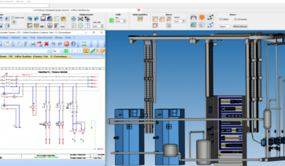
During the loop design process, essential information is organized in the form of lists in a spreadsheet, such as Excel. These lists can be created by extracting data from P&IDs (using the SchemPID software), calculators, or by directly inputting them online.
On the other hand, standard plans are defined using the powerful drawing and schematic tools of the SchemELECTsoftware. These standard plans serve as references to structure the loops and ensure their coherence.
To facilitate the association between standard plans and data from loop files, equivalences are established. These equivalences link the information present in the standard plans with the specific data from the loop files, ensuring clear understanding and optimal loop management in the design process.
Thanks to this systematic approach and interoperability between different software, loop design becomes smoother and more precise, allowing you to create efficient and well-documented instrumented systems.
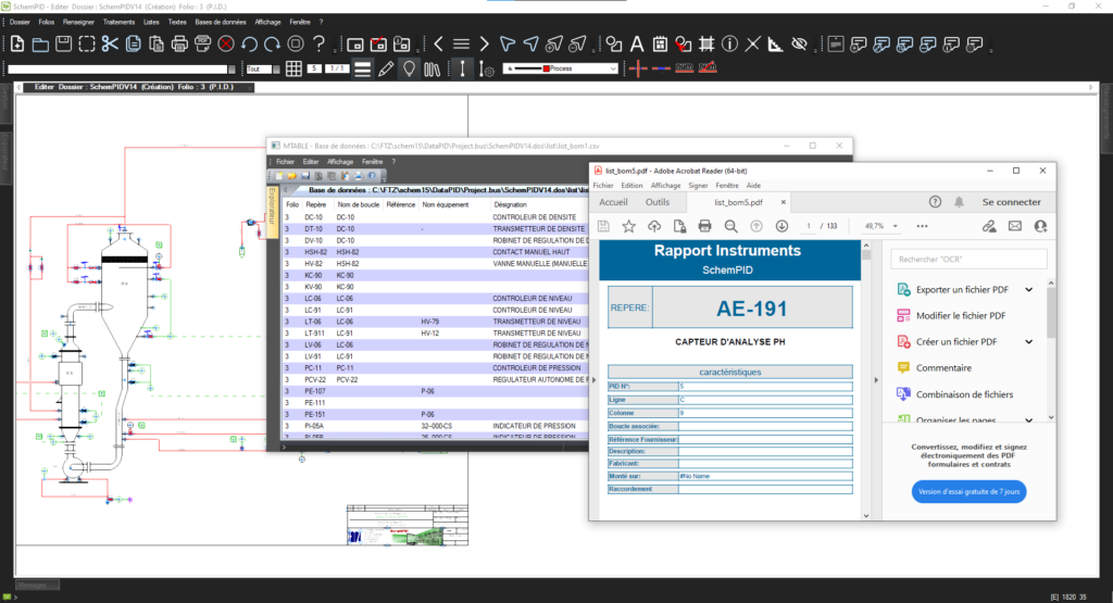
SchemPID is an advanced software that simplifies the generation of material lists in P&ID schematics. It offers seamless integration with supplier databases, allowing quick access to necessary information. Thanks to this feature, numerous nomenclature standards can be generated simultaneously, providing great flexibility in selecting component bases and their attributes.
The material lists generated by SchemPID can be directly implemented on the project’s sheets, ensuring dynamic updates in case of modifications. This feature maintains information consistency throughout the design process. Additionally, the software offers the option to generate customizable lists for lines, equipment, loops, and even datasheets.
With SchemPID, generating material lists becomes fast, efficient, and customizable. It enables you to optimize your work by automating repetitive tasks and providing precise and comprehensive information. Whether you are working on complex or large-scale P&ID projects, SchemPID is the ideal tool to manage your material lists with ease and reliability.
SchemPID offers a wide range of features to facilitate the creation of P&ID diagrams. It comes with comprehensive libraries of P&ID, hydraulic, and pneumatic symbols, allowing you to accurately represent various components of your system.
Another important feature of SchemPID is its integration with manufacturer databases. This allows you to access a wide range of components from different manufacturers and use this information to generate precise bill of materials. This ensures that you are using up-to-date data that complies with industrial standards.
SchemPID also provides the option to customize your title blocks and backgrounds by integrating your own logos. You can choose from various image or drawing formats for optimal customization. Additionally, the software allows you to manage cross-references according to your working method, ensuring consistency and efficiency in your documentation.
With SchemPID, you have a comprehensive tool that helps you create accurate P&ID diagrams, integrate components from different sources, and customize your documents according to your specific needs. Whether it’s for small or large-scale projects, SchemPID meets your requirements for industrial schematics.
Additional information
Macro language
Macro language
SchemPID has a macro programming language that can be used to customise automatic processes :