A study of industrial processes generally begins with the general diagram during the preliminary project in the form of PFD (Process Flow Diagram) or in French PCF (Plan de circulation des fluides), defining the products and their routing in the piping and the various main equipment.
Then, the process is detailed by the realization of piping and instrumentation diagrams
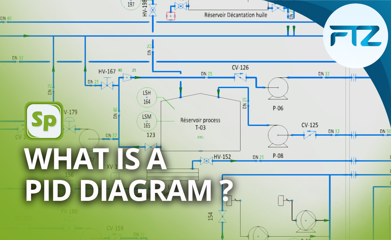
A piping and instrumentation diagram, commonly abbreviated as P&ID (Piping and Instrumentation Diagram), is a schematic illustration of all the functional relationships between the piping environment, instruments and various equipment in an industrial process.
It is a very important schematic that allows to set up a new industrial installation, to optimize an existing process or to replace an equipment
PID diagrams are used as a working basis for many actors of the industrial process such as engineers, operators, technicians or project managers.
PID diagrams identify the various principles that make up the entire industrial process: mechanical equipment, control and measurement elements, fittings, insulation and protection, as well as the coordination of the installations with each other.
A PID diagram, standardised and accurate representation of industrial processes
All the elements present on a P&ID diagram such as valves, pumps, fittings, containers, flanges, tanks, actuators, valves, electrical or hydraulic components… are represented in the form of symbols.
The pipe networks are defined by interconnected lines taking into consideration the diameter, the identification number and the class of the pipes and circuits.
A real communication and synergy tool between the different industrial operations of risk analysis, development, construction and maintenance, a PID diagram must be meticulously conform to reality.
A PID diagram integrates the following elements:
- All mechanical equipment with names and numbers
- Gates and their identification
- The diameters and markings of the process piping
- The projection of vents, pipes, special fittings, reductions or enlargements
- Permanent start and purge lines
- Flow directions
- The referencing of interconnections
- The inputs and outputs of the controls and their interlocking system
- Seismic category
- The class change interfaces
- The quality level
- Signal inputs and the computer control system
- Supplier and stakeholder interfaces
- Identification of third-party components and subsystems
- The planned physical sequence, classification and/or capacity of the equipment
A fundamental document that allows a logical progression of industrial engineering processes, PID diagrams are generally designed using CAD software.
Depending on the quantity, complexity or degree of modifications to be made, dedicated CAD software may be required.
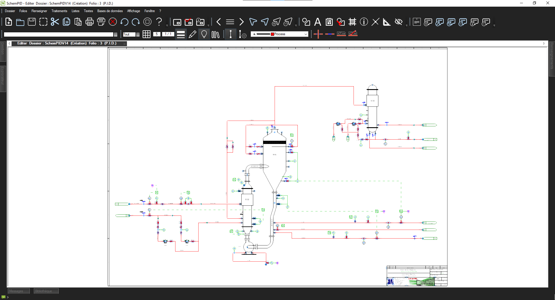
Why choose SchemPID for your P&ID diagrams?
SchemPID is a software designed and published by the company FTZ. It is dedicated to the design of fluid flow diagrams, Process and Instrumentation diagrams and hydraulic and/or pneumatic diagrams.
In addition to its capabilities to integrate all business functions and create a schematic interconnection, SchemPID CAD software generates automatic pipe and instrument numbering, datasheet representation, library and manufacturer data customization, automatic list and bill of materials extraction.
SchemPID offers a flexible, accessible and ergonomic interface to meet all current industry standards, ISA, ISO, NF, IEC, ANSI.
With SchemPID, FTZ provides a CAD software that benefits from a technical support service and accompaniment in training and customization. With its functions and ergonomics, the SchemPID computer-aided design tool is one of the most powerful in this field.