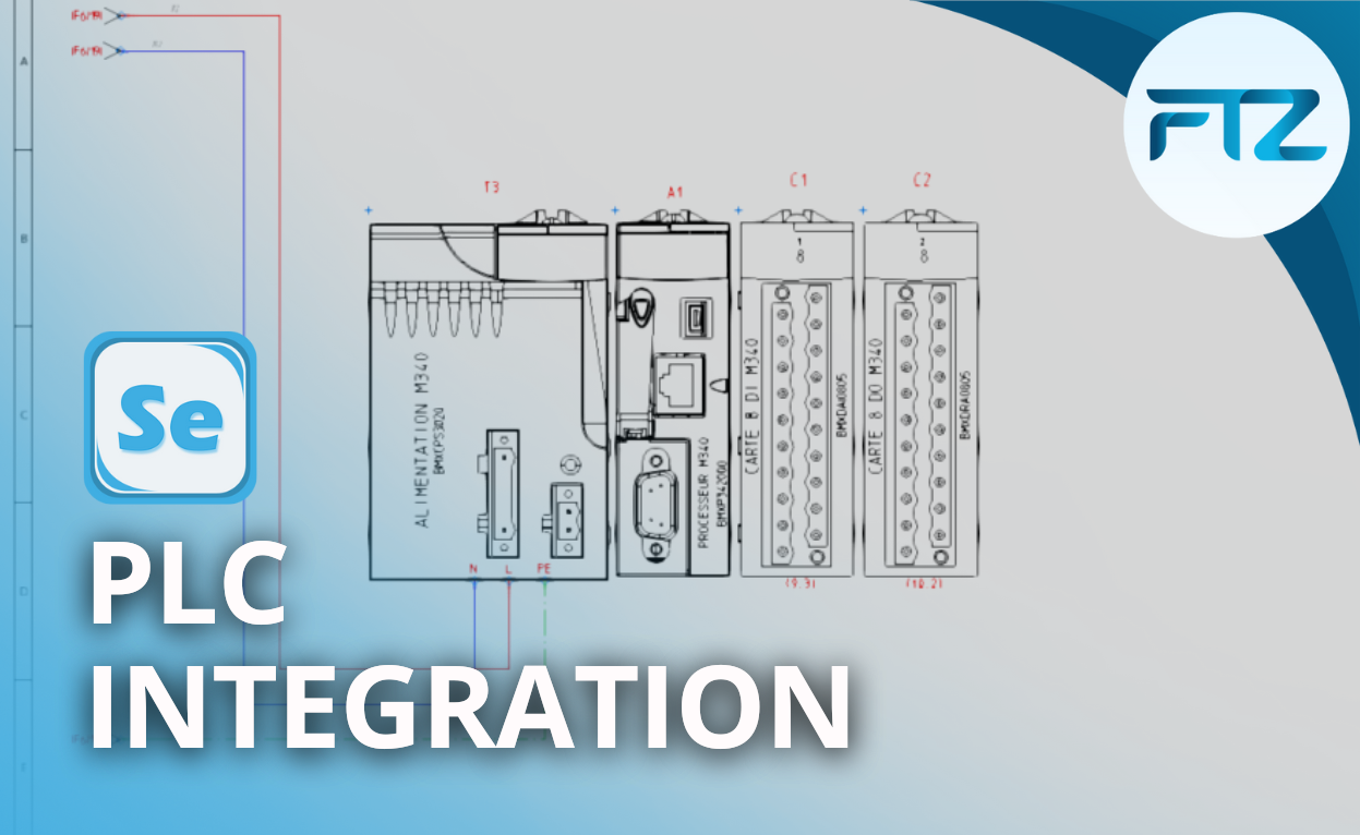
How can I easily create electrical diagrams of the PLC boards?
In the vast majority of industrial projects, the integration of PLCs is a crucial stage in guaranteeing the fluidity of exchanges between wiring and system programming. Thanks to the PLC module integrated into our SchemELECT electrical CAD software, this task becomes not only intuitive but also highly optimised. Discover how SchemELECT facilitates this operation thanks to its advanced functionalities.
Complete automation for considerable time savings
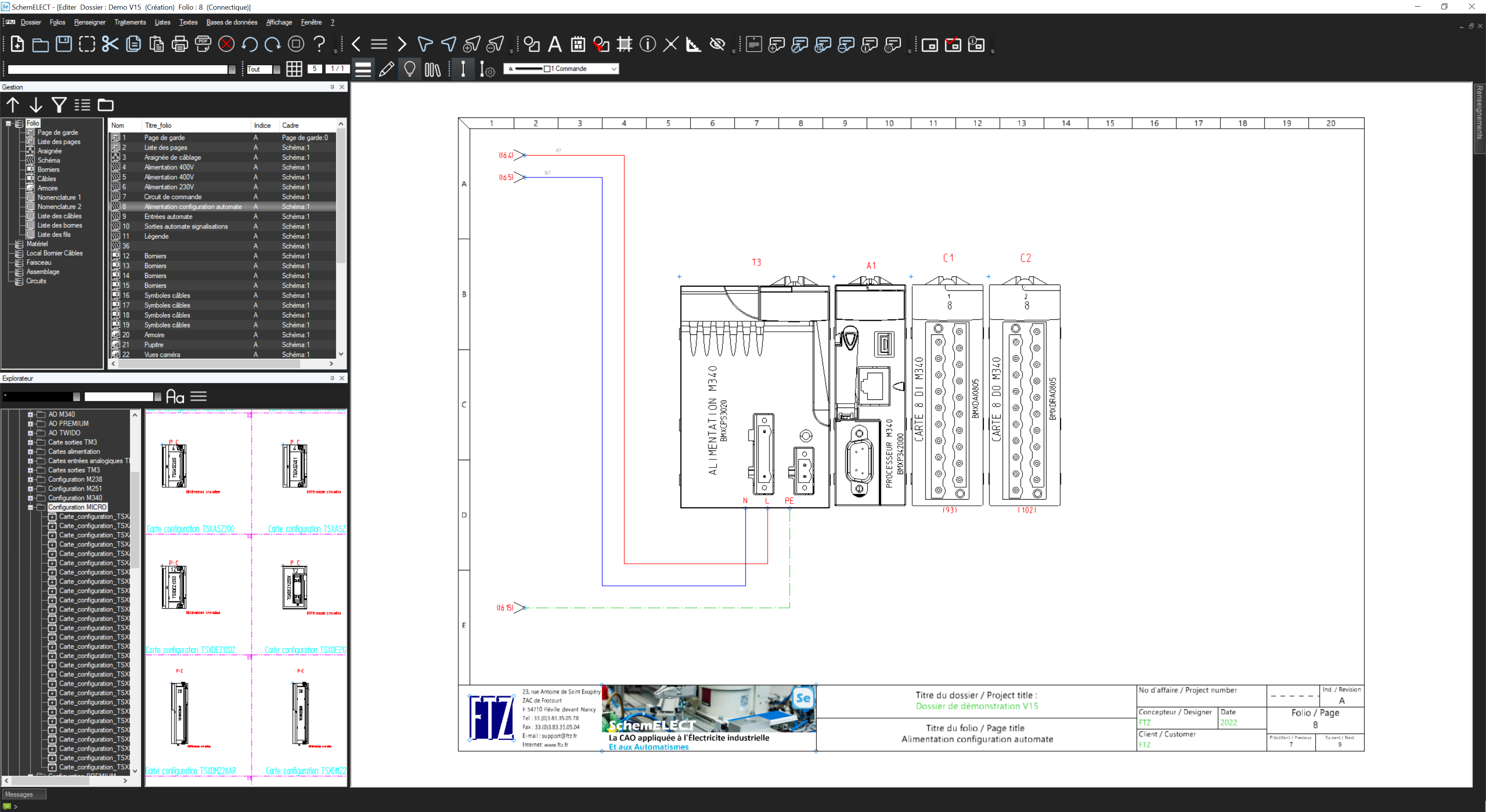
SchemELECT‘s PLC module is specially designed to facilitate the exchange of information between PLC programming consoles and CAD software.
This module allows you to define the PLC configuration (PLC, rack, boards) and automatically generate schematic sheets of PLC boards in just a few seconds.
With this functionality, data linked to inputs/outputs and provided by the automation engineers is directly integrated into the board schematics, such as mnemonics, comments and other attributes.
To take things even further, you can also add the name of the standard diagram linked to the different lanes to the spreadsheet, so that they are automatically displayed on the diagram.
No need to enter information manually! Each lane is clearly represented, either by grouping this information on the map or by separating each lane on the diagrams.
Intuitive management thanks to dynamic cross-referencing
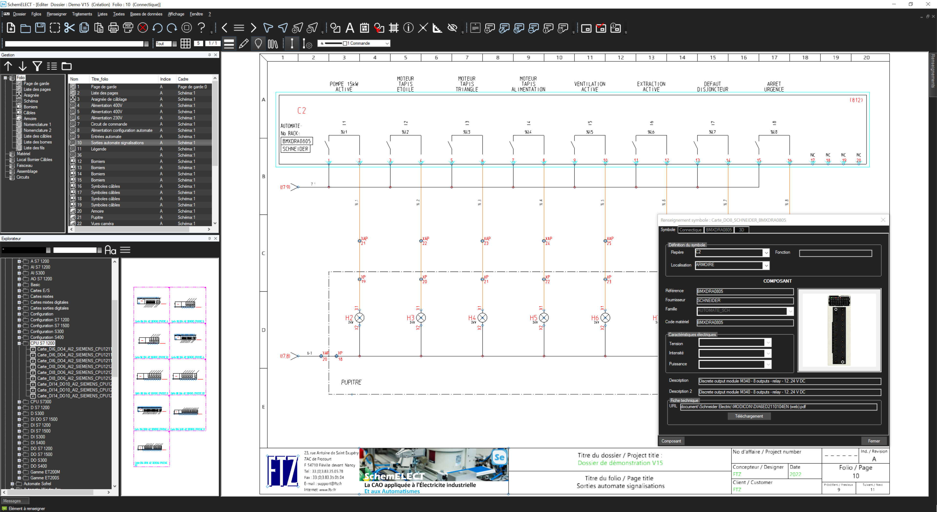
The integration of a PLC is not limited to data entry: it is just as essential to be able to navigate easily between the different elements.
SchemELECT includes a dynamic cross-referencing system that simplifies this task. Thanks to this feature, you can quickly locate map and PLC tracks directly on the schematic. A simple click is all it takes to move from one element to another, making navigation fluid and intuitive.
This system is particularly useful for complex projects requiring a clear overview and precise traceability.
Graphic and precise customisation
One of the major advantages of the PLC module is its ability to offer a complete and personalised graphical representation.
This visual clarity is essential for :
– Guarantee smooth communication between the design and programming teams
– Reduce the risk of errors associated with schematic interpretation
– Speed up the validation and commissioning phases of projects
Optimised interaction with programming consoles
With SchemELECT‘s PLC module, PLC integration is not only fast, but also interactive with programming consoles. If the electrical diagrams are drawn up beforehand, the data extracted from SchemELECT can also be used directly by the automation engineers, avoiding manual re-entry and the associated errors.
This smooth, automated process ensures that your schematics accurately reflect the actual configuration of your PLCs and their components, offering greater efficiency at every stage of the project.
Why choose SchemELECT for PLC integration ?
SchemELECT stands out for :
– Ease of use: an intuitive interface that makes it easy to learn, even for complex projects
– Automation: Reduced manual tasks thanks to automatic generation of map folios
– Accuracy: Dynamic cross-referencing and a complete graphical view for better understanding of diagrams
– Time-saving: interaction between CAD data and programming consoles.
Conclusion: Integrate your PLCs easily with SchemELECT
With SchemELECT‘s PLC module, integrating a PLC into electrical CAD has never been easier. By combining automation, visual clarity and advanced navigation tools, SchemELECT turns a complex task into a quick and intuitive process.
Ready to optimise your electrical projects with SchemELECT ? Contact us today for a demonstration or to find out how our solutions can be adapted to your needs.