Reading industrial electrical diagrams is an essential skill for electricians, automation engineers and design offices. Whether analysing an existing installation or designing a new project, understanding the structure of a diagram is essential.
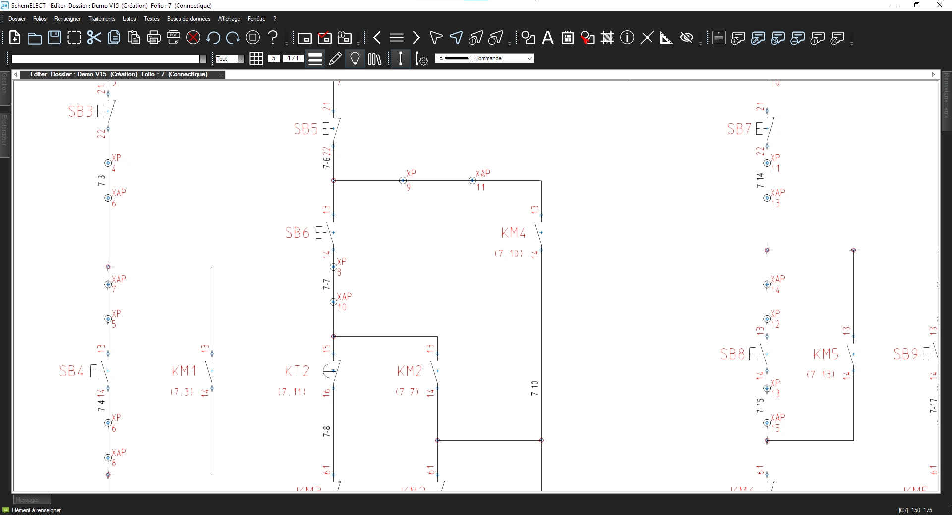
Today, specialised software such as SchemELECT not only allows you to read electrical diagrams, but also to create, modify and automatically check them according to local standards.
What is an electrical diagram ?
An electrical diagram is a graphical representation of a circuit.
It uses standardised symbols to represent, among other things :
- Power sources
- Protective devices (circuit breakers, fuses)
- Control devices (contactors, relays)
- Receivers (motors, lighting, resistors)
- Connections between components
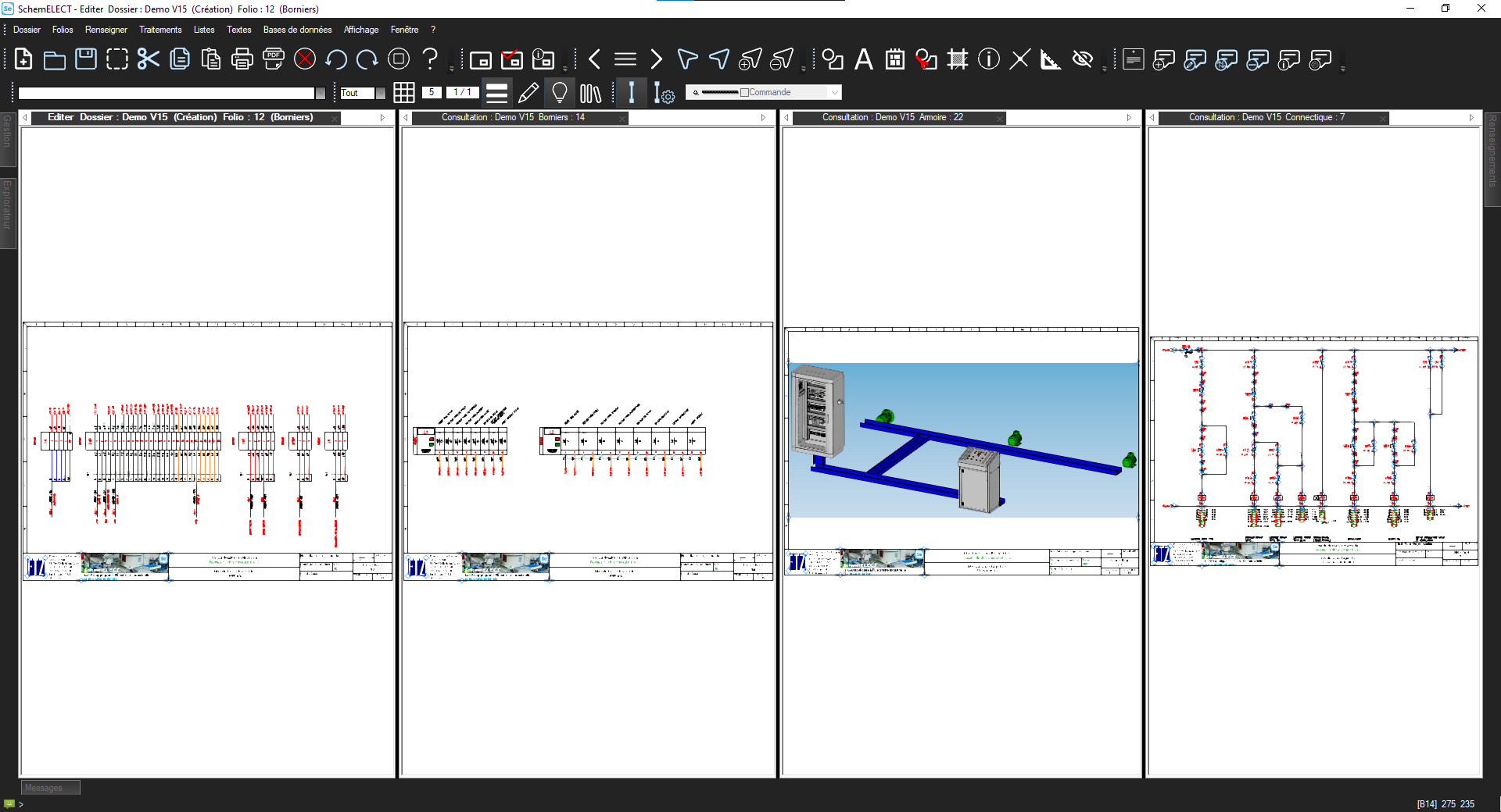
Electrical diagrams are often supplemented by :
- PLC cards
- Representations of terminal blocks and cables
- Cabinet layout
- Parts lists
A diagram does not show the exact physical reality of the wiring, but rather the operating logic of the circuit.
The main types of electrical diagrams
Single-line diagram
This represents all conductors as a single line.
It is used to provide a quick overview of an installation.
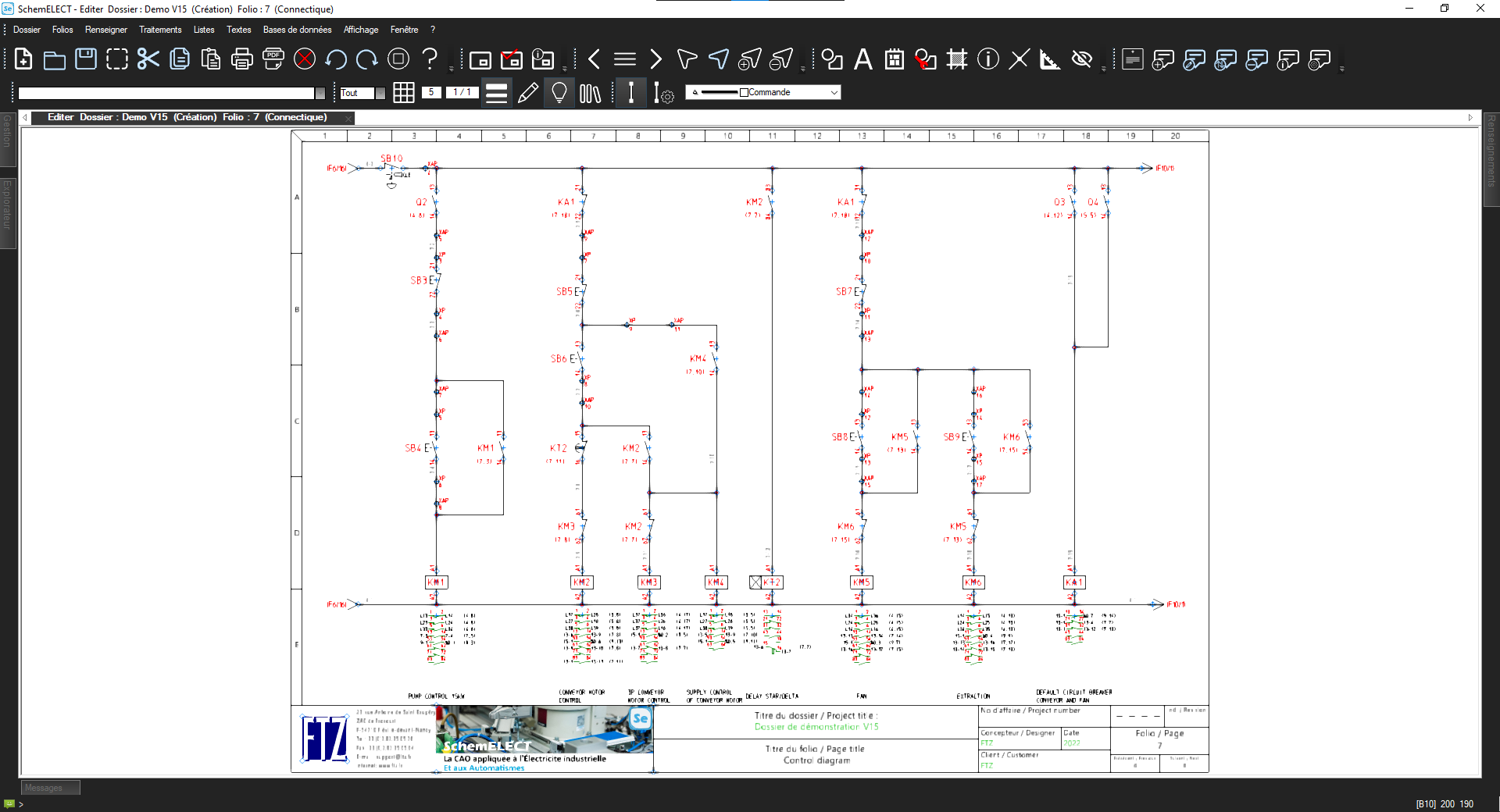
Multi-line diagram
Each conductor is represented individually.
This type of diagram is more accurate and is often used for industrial wiring.
The schematic diagram
This highlights the logical operation rather than the physical wiring.
With SchemELECT, these different types of diagrams can be generated and organised automatically within the same project.
How to read an electrical diagram effectively ?
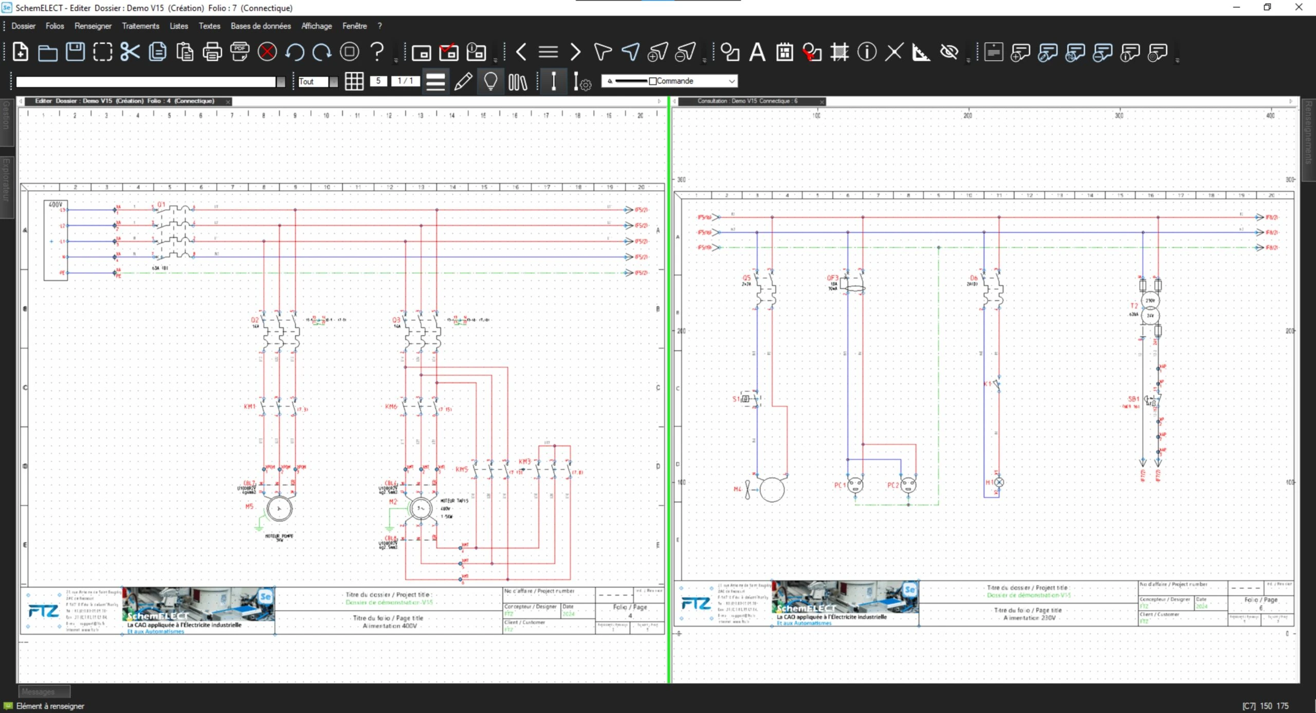
- Identify the power supply
Locate the power source (230 V, 400 V, direct current, etc.).
In SchemELECT, voltage and location information is clearly indicated in the project properties.
- Locate the protective devices
Circuit breakers, disconnectors, fuses: these are generally located upstream of the circuits.
The software allows you to check their consistency and referencing.
- Follow the path of the current
A diagram is generally read from left to right and from top to bottom.
With SchemELECT, automatic marking makes it easy to follow the connections.
- Identify control devices
Contactors, relays, push buttons, etc.
The software automatically manages contact references and cross-references.
- Check annotations
Wire identification, terminal numbering, parts lists.
SchemELECT automates these elements to limit human error.
The importance of standards
Electrical diagrams must comply with specific standards (CEI/ANSI/BS/JIS).
The use of specialised software guarantees:
- The use of standardised symbols
- Consistent labelling
- Automatic generation of parts lists
- Reduction in errors
SchemELECT integrates these standards directly into its design environment.
Why use SchemELECT for your electrical diagrams ?
Reading a diagram is one thing.
Designing it efficiently, modifying it quickly and avoiding errors is another.
With SchemELECT, you benefit from :
- An environment dedicated to industrial electrical diagrams
- Automatic functions for marking and numbering
- Integrated consistency checks
- Increased productivity for design offices
The software does more than just draw: it structures and secures your electrical project.
Conclusion
Knowing how to read an electrical diagram remains a fundamental skill.
But in a modern industrial context, using a tool such as SchemELECT allows you to go further: rapid design, regulatory compliance and error reduction.